|
EPEVER Tacer Serie A/B Datalogging mit Raspberry PI oder Linux PC |
EPEVER Tacer Serie A/B Datalogging with Raspberry PI or Linux PC |
|
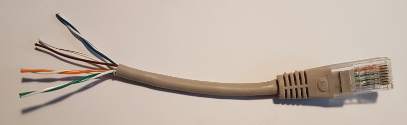
1. Das Kabel Zum Anschluss eignet sich ein einfaches (älteres) Netzwekkabel mt RJ45-Steckern. Den einen Stecker habe ich abgeschnitten und Die Hülle auf ca. 3cm entfernt. Es kommen 4 verdrillte Adernpaare zum Vorschein http://www.netzmafia.de/skripten/netze/twisted.html |
1. cable to connect a computer to Tracer You can use a ethernet cabel with RJ45 plug. The plug at one size I cutted off so there are four pairs of wires. They are described on http://www.netzmafia.de/skripten/netze/twisted.html |
|
2. Verbindung zu Tracer A/B Unter auf Seite 13 findet man die Steckerbelegung Tracerseitig. Daraus ergibt sich folgende Belegung: 8 br Ground 7 br/ws Ground 6 gr, A 5 ws/bl A
3 ws/gr B 4 bl, B 1 sollen nicht verwendet werden 2 sollen nicht verwendet werden
|
2. Connection to Tracer A/B There is a documentation of Tacer Seies A/B Page 13 describes the connections of the plug. 8 br Ground 7 br/ws Ground 6 gr, A 5 ws/bl A 4 bl, B 3 ws/gr B 1 do not use 2 do not use |
|
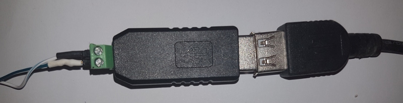
3. Verbindung zum Rechner Die Datenschnittstelle des Tracer A/B verwendet RS485 mit Modbus-Protokoll. Es hat meiner Meinung nach keinen Sinn, die Leitungen A und B direkt mit den UART- oder GPIO-Pins des Arduino oder Raspberry zu verbinden. Erfolgreich habe ich einen RS485 zu USB-Konverter, basierend auf dem Chip ch341, den es für wenig Geld bei ebay gibt, genutzt, um Tracer und Ubuntu-PC bzw. Raspberry miteinander zu verbinden. Auf der Rückseite der Schaubklemmen sind die Kontakte mit A und B beschriftet. Ich habe ws/bl auf A und bl auf B belegt. Das Gerät sollte als /dev/ttyUSB0 oder /dev/ttyUSB1 verfügbar sein. lsusb: Bus 001 Device 014: ID 1a86:7523 QinHeng Electronics HL-340 USB-Serial adapter
dmesg: [3814117.151241] usb 1-1.3: New USB device found, idVendor=1a86, idProduct=7523 [3814117.151252] usb 1-1.3: New USB device strings: Mfr=0, Product=2, SerialNumber=0 [3814117.151257] usb 1-1.3: Product: USB2.0-Serial [3814117.151953] ch341 1-1.3:1.0: ch341-uart converter detected [3814117.159303] usb 1-1.3: ch341-uart converter now attached to ttyUSB0 |
3. Connection to PC or RaspberryPi There is a RJ45 Socket at the bottom of Tracer Series A/B using Modbus protocol. I connected the Lines A and B to to RS485 to USB converter based on chip ch341 showed above. It is online available as a low price product , I bought it via ebay. I connected wire white/blue to A and blue to B at the RS485-USB-Converter. When the USB-plug is connected with the PC You should see it as device /dev/ttyUSB0 or / dev/ttyUSB1. lsusb: Bus 001 Device 014: ID 1a86:7523 QinHeng Electronics HL-340 USB-Serial adapter
dmesg: [3814117.151241] usb 1-1.3: New USB device found, idVendor=1a86, idProduct=7523 [3814117.151252] usb 1-1.3: New USB device strings: Mfr=0, Product=2, SerialNumber=0 [3814117.151257] usb 1-1.3: Product: USB2.0-Serial [3814117.151953] ch341 1-1.3:1.0: ch341-uart converter detected [3814117.159303] usb 1-1.3: ch341-uart converter now attached to ttyUSB0 |
|
4. Software Bei umfangreicher Recherche zu Software zum Logging der Daten von Tracer Ladereglern waren hauptsächlich Lösungen, basierend auf MT5-Protokoll zu finden. Mit den Geräten der Serie A/B scheint das nicht zu funktionieren. Das Protokoll für Tracer A/B ist sehr gut unter dokumentiert. Der erste Unterschied zum MT5-Protokoll liegt in der BAUD-Rate von 115200 Baud. Der zweite Unterschied besteht darin, dass die Prolog- und Synchronisationsbytes offenbar wegfallen. Es wird nur der Befehl, beginnend ab der DeviceID und endend mit der CRC Prüfsumme übertragen. Der dritte Unterschied scheint in der Berechnung der CRC Prüfsumme zu liegen. Alle Funktionen, die ich in diversen Foren in Beispielen gefunden habe, lieferten andere Prüfsummen, als in den Beispielen aus der Dokumentation. Der erste Erfolg stellte sich mit der Übertragung der Befehlssequenz aus der Doku, s. 12 zum Lesen der Batteriespannung ein (01 04 31 04 00 01 7E F7). Unter https://crccalc.com/ fand ich ein sehr brauchbares tool zum Berechnen der CRC. Mit der Einstellung Hex und Eingabe der Befehlssequenz ohne Leerzeichen und ohne CRC ergab sich unter CRC16 / Modbus schließlich die richtige CRC. Nun konnten auch andere Befehle codiert und mehrere Register erfolgreich gelesen werden. Dabei wurde die CRC mit crccalc berechnet und in den SendeDatenpuffer eingesetzt. Weitere Recherchen führten zu https://ctlsys.com/support/how_to_compute_the_modbus_rtu_message_crc/ Hier findet sich der Algorithmus schon fix und fertig in c zur erfolgreichen Berechnung der CRC. Sie muss nur noch in der richtigen Byteorder in der Puffer eingesetzt werden. Als Basis erwies sich die Lösung von https://github.com/StereotypicalSquirrel/TracerComms als eine gute Grundlage. Die Funktionen aus tracer.h/tracer.c habe ich nicht verwendet, wohl aber die Funktionalität aus rs232.
|
4. Software There are a lot of posts discussing data logging for Tracer charge controllers. Most of them based on protokol of MT-5, the remote controll unit of older Tracer chage controllers. The newer Tracer Series A/B use the MT-50 remote Controller with a different communication protocoll. There is a documentation The differences are buadrate 115200 insteed of 9600 (MT-5) No prolog and no synchonisation bytes, the datagram to send contains the device id (one Byte), the command (one Byte), the starting register (two Bytes in big endian format), number of registers (two Bytes in big endian format) and crc(two bytes in little endian format). The calulation of CRC seems to be different. There is a CRC calulator on a website https://crccalc.com/ The documentation above contains a example. The command asks the chargecontroller to send the battery votage. (01 04 31 04 00 01 7E F7). Sendig this command shold work with the right wiring. At https://ctlsys.com/support/how_to_compute_the_modbus_rtu_message_crc/ I found a function calculating the right CRC. My own experiences I made, were based on https://github.com/StereotypicalSquirrel/TracerComms, thanks to John Burns. This Solution works with Tracer-MT-5 Protocol, so someting had to be changed. It provides Communication by RS232. The functions in tracer.h/tracer.c I didn‘t use. Main.c I used as playground to do a lot of trys. So I added the CRC-clulation function and for debugging a hexdump of sending/receiving buffer. I am reading fom 0x3100 16 Registers and then I store the values temporally in an array of flaots. Then I‘am writing the data as CSV-values in a dayly outputfile. |
arnold.beck@web.de